Study Advanced Optical Elements
- Typically an experimental setup needs at least one fancy optical component, which makes a setup special. Here I try to cover all components I worked with, making sure that a student understands basic idea behind and possible applications.
- Last Updated: Jan 20, 2024
- Published: Mar 15, 2023
Table of Contents
Resources
Some useful resources:
- rp-photonics
- wikipedia
- Technical note on EOMs
- photodiode tutorial from Thorlabs
Questions
Resonators
- What is finesse, FSR, and a quality factor?
- How to use it as a filter?
- Different resonator designs: Fabri-Perot, bow-tie.
- Ultrastable resonators: materials used and linewidths achieved?
- What is basics of PDH locking?
- Running wave vs standing wave solution
Electro-optical modulator
- What is an EOM?
- How is it used?
- Which different types of modulation is there?
- How modulation is applied?
- Its applications and limitations?
Spatial light-modulator
- Different types of SLMs
- Correction phase
- Fourier or direct imaging?
- Examples of usage and its limitations
Spectral filtering techniques
- Lens cavity
- Resonant atoms
- fiber bragg-gratings
Photodetectors
- Definition
- Important imperfections of a photo-diode
- Junction capacitance
- Dark current
- Shunt resistance
- Series resistance
- Schematic with all these elements included
- Important parameters to keep in mind when choosing a diode
- Response time/ bandwidth
- Responsivity of a diode
- Saturation power
- What is a gain/bandwidth product?
- Simplest schematic of a PD
- Terminating resistance
- Transimpedance amplifier circuit
Piezo-actuators
- Principle of work
- When to use it
- How to use it?
Single-photon detectors
- Principle of work?
- How not to burn it?
- Signal counter
- Typical characteristics?
Homodyne detectors
- Principle of work?
- Schematic design explained
- Examples of applications
Motorized knobs
- What are those?
Telescopes (exchange with AOMs!)
Answers: in progress
Resonators: answers
- Finesse, FSR, and Quality Factor:
- Finesse is defined as the ratio of the free spectral range (FSR) to the full width at half maximum (FWHM) of the resonance peak. Is a measure of how many times a photon can oscillate back-and-forth before it decays and leaves a cavity.
- Free Spectral Range is the separation in optical frequency between two consecutive resonances in a resonator. It is inversely proportional to the round-trip optical path length of the cavity.
- Quality Factor (Q): Quality factor is a dimensionless parameter representing the sharpness of a resonance. It is the ratio of the resonant frequency to the FWHM and is related to finesse by the formula
- Using resonator as a filter: Higher finesse values indicate a narrower linewidth and better frequency discrimination. In applications like optical filtering, high finesse resonators are used to transmit a narrow range of frequencies, acting as a spectral filter.
- Different Resonator Designs:
- Fabry-Perot Resonator: Consists of two highly reflective mirrors facing each other. Light undergoes multiple reflections between the mirrors, forming standing waves and creating a series of resonances.
- Bow-Tie Resonator: A variant of the Fabry-Perot cavity where four mirrors are placed to make light in a bow-tie shape. Typically is used in lasers with nonlinear crystals.
- whispering gallery resonator
- Ultrastable Resonators: Materials: Ultrastable resonators often use low-expansion materials like fused silica or ultra-low expansion glass ceramics to minimize thermal effects. Linewidths: Achieving ultrastable resonators involves careful temperature stabilization and control, leading to linewidths in the sub-Hertz range or even lower.
- Basics of Pound-Drever-Hall (PDH) Locking: PDH locking is a technique used to stabilize the frequency of a laser to a resonant cavity. A modulated sideband is introduced to the laser light, and the cavity-induced phase modulation is used to create an error signal. The error signal is then fed back to the laser frequency to lock it to the cavity resonance, providing high stability.
- Running wave vs. standing wave resonator
- Running Wave: In a running wave resonator, the incident and reflected waves interfere to form a traveling wave within the cavity. The interference pattern continuously moves through the cavity.
- Standing Wave: In a standing wave resonator, the interference pattern creates a stationary, standing wave within the cavity. Fabry-Perot cavities often operate in a standing wave configuration, where the standing waves determine the resonant frequencies. Understanding these concepts is crucial for designing and utilizing optical resonators in various applications, ranging from precision metrology to laser stabilization.
- Stability conditions.
Electro-optical modulator: answers
- What is an EOM? An Electro-Optical Modulator (EOM) is a device that modulates the intensity, phase, or polarization of light using an electric field. It utilizes the electro-optic effect, where the refractive index of a material changes in response to an applied electric field, to manipulate the properties of the transmitted light.
- EOM’s applications
- quick switching
- shifting frequency to frequencies, which are too high for AOMs
- quickly adjustable waveplate
- in laser systems they are used for Q-switching, mode locking, and frequency modulation.
- Which different types of modulation is there?
- Amplitude Modulation (AM): EOMs can modulate the intensity of light, resulting in AM. This is achieved by varying the amplitude of the electric field applied to the EOM, which in turn changes the refractive index and the intensity of the transmitted light.
- Frequency Modulation (FM): By modulating the frequency of the applied electric field, EOMs can induce changes in the optical frequency of the transmitted light, leading to FM.
- Phase Modulation (PM): EOMs can modulate the phase of light by applying a varying electric field. Changes in the refractive index cause corresponding changes in the phase of the transmitted light.
- Phase-modulation
- What happens to spectrum?
Let’s assume sine phase modulation, that electric field has form:

Phase modulation creates infinite series of sidebands with amplitudes proportional to bessel functions. - How to get maximum in the first sideband?
Typically we are interested in the first sideband and a way to transfer power into it. Fraction of power which is left in the carrier as a function of modulation depth
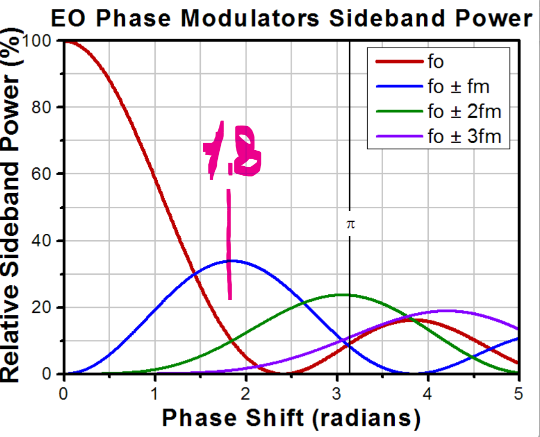 We see that there is an optimum of power transfer, which happens at phase shift of 1.8 radians. Power that is transferred to the first-order sidebands is about 34%.
- What happens to spectrum?
Let’s assume sine phase modulation, that electric field has form:
- Parameters from a datasheet?
- Insertion loss
- extinction
- Free space vs fiber coupled options? There are free-space and fiber options.
- What do I need to setup EOM?
As for an AOM you need a signal generator, an amplifier, and fiber alignment. If you are doing phase/frequency modulation, you would typically need to filter out all unnecessary frequency components. One of the possible combinations for usage with Rb87 hyperfine splitting (6.7 GHz). A fiber-coupled EOM (NIR-MPX800-LN-10, iXblue). The 6.8 GHz microwave driving signal is derived from the PLL frequency synthesizer ADF5355 (EV-ADF5355SD1Z Analog Devices Inc), and subsequently amplified by MiniCircuits ZVE-3W-83+ to achieve optimal sideband power.

A setup to drive EOM and achieve a single sideband. - Limitations Typically fiber coupled EOMs have stringent limitations on input optical power.
- What is a QAM modulator? QAM stands for quadrature amplitude modulation. This type of modulator allows to create sideband and eliminate the carrier, so basically shifting frequency. I haven’t seen it for 780 wavelength, but exists for communicational wavelengths (1550nm).
Spectral filtering techniques: answers
- Lens cavity
- Atomic transition
- There exist fiber bragg gratings IXC-FBG-PS-795-1-ATH-PM-FA - iXblue and other company
Spatial-light modulators: answers
- Different types of SLMs
- Liquid Crystal Spatial Light Modulators: These use liquid crystal materials to modulate the phase or amplitude of light.
- Deformable Mirror Spatial Light Modulators: These SLMs use a deformable mirror surface to control the phase of incident light.
- Micro-Electro-Mechanical Systems Spatial Light Modulators: Micro-Electro-Mechanical Systems technology is employed to create tiny movable mirrors, providing precise control over the reflected light for applications like laser beam steering and projection displays.
- Digital Micromirror Devices (DMDs): DMDs consist of an array of tiny mirrors that can be individually tilted to control the reflection of light.
- Correction Phase: Correction phase refers to the adjustment of the phase of light to compensate for aberrations or distortions in optical systems. Spatial-light modulators are often used to dynamically correct phase errors in real-time, improving imaging quality or beam characteristics.
- Fourier or Direct Imaging:
- Fourier Imaging: In Fourier imaging, an SLM is used to modulate the spatial frequency content of an optical wavefront, enabling operations in the Fourier domain. This is useful for applications like Fourier-transform spectroscopy.
- Direct Imaging: In direct imaging, SLMs are employed to manipulate the amplitude or phase of light, allowing for real-time control over images or patterns.
- Examples of Usage and Limitations. Usage Examples:
- Holography: SLMs play a crucial role in generating and reconstructing holographic images.
- Adaptive Optics: Used in astronomy and microscopy to correct for atmospheric distortions or optical aberrations.
- Digital Holographic Microscopy: Enables three-dimensional imaging of biological specimens.
- Optical Tweezers: SLMs can be used to shape and control optical traps for manipulating microscopic particles. Limitations:
- Limited Pixel Resolution: The achievable resolution of the modulated patterns may be limited by the pixel density of the SLM.
- Limited Phase Wrapping Range: Some SLM technologies may have limitations in the range of phase modulation they can achieve, leading to phase wrapping issues.
- Complex Calibration: Calibration and alignment processes can be complex, impacting the ease of use in some applications.
- Cost: High-quality SLMs can be expensive, particularly for applications requiring high resolution and fast response times. Understanding the specific characteristics and limitations of different types of SLMs is crucial for selecting the most suitable device for a given application.
- How to work with DMD
I will describe our experience to work with DLP SuperSpeed V-Module V-7001.
- The main characteristics of the device? It consists of 2D array of programmable mirrors. The size of acitve area is 768 by 1024 pixels (14.5 by 10 mm). Each mirror has dimensions 12.59 um times 12.59 um, in between mirrors the spacing is 1 um (See picture). You can tilt each mirror to be on or off: by tilting each mirror across diagonal by 12°. Works with visible wavelengths and the its switching rate is 290 Hz.
- Diffraction You need to understand how to control an amplitude and a phase of generated image. You can directly work with the device by switching on the pixels which are required (direct imaging). If you need to embed phase information on your beam, you would work with DMD as with a diffraction grating (See picure).
- Phase map We found it helpful to measure phase map or imperfections of the device. For this we split the screen into pathces and while keeping one in the same spot the second patch is scanned across the whole area. These two pathes are made to interfere and the interference pattern is read out (See picture).
Photodetectors: answers
- Definition A photodetector, or photodiode, is a semiconductor device that converts light into an electrical current. When exposed to photons, the photodiode generates an electric charge proportional to the incident light intensity.
- How to convert current into voltage? Indeed a photodiode generates current, but we typically measure voltages. There are two ways to convert it: connecting it to a terminating resistance (1) or connecting it to a transimpedance amplifier (2).
- Terminating resistance will result in a voltage:
- Transimpedance amplifier circuit includes an opamp, which allows you to convert current into voltage and amplify signal simultaneously. The resultant voltage is

Transimpedance amplifier circuit.
- Terminating resistance will result in a voltage:
- What are two modes of operation of a PD? Photoconductive (reverse bias) and photovoltaic (zero-bias).
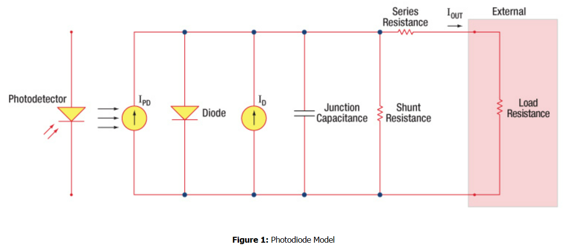
- Imperfection of a PD?
- Junction Capacitance. The capacitance associated with the depletion region of the photodiode. It affects the photodiode’s response time.
- Dark Current. The current flowing through the photodiode in the absence of light, caused by thermal generation of electron-hole pairs.
- Shunt Resistance. The parallel resistance in the photodiode circuit, influencing the dark current.
- Series Resistance. The resistance in series with the photodiode, affecting the diode’s response time and linearity.
Schematic of non-ideal photodetector, taken from here.
- Parameters of a PD?
- The response time of an optical detector refers to the time it takes for the detector to respond to changes in the incident light intensity. It is typically measured as the time taken for the detector output to reach a certain percentage (e.g., 90% or 95%) of its final value after exposure to a step change in light.
- Saturation power is the maximum optical power level that a detector can handle without its output saturating or reaching a plateau.
- Responsivity of a diode refers to the electrical output response of the diode to incident optical power, the ratio of the electrical current or voltage generated by the diode to the incident optical power:
- What is the gain/bandwidth product? It is a figure of merit for the performance of an amplifier, indicating the trade-off between gain and bandwidth. In photodetector applications, it is crucial to balance the trade-off between achieving higher gain and maintaining a sufficient bandwidth for the application.
Piezo-actuators: answers
- Principle of work: Piezo-actuators operate based on the piezoelectric effect, where certain materials (such as piezoelectric crystals) undergo mechanical deformation in response to an applied electric field. When a voltage is applied to the piezo-actuator, expands or shrinks producing mechanical displacement. This property allows piezo-actuators to provide precise and rapid movements in response to electrical signals.
- When to use it? They are used inside of lasers and in other resonators. Piezo-actuators are particularly useful in applications requiring high precision, fast response times, and fine positional control.
- What to remember when setting it up?
- Typically you need to supply a high-voltage signal (50–100 V).
- Some of them require only positive polarity.
- To keep specific displacement you would need to keep your voltage supply always on.
- beware that it has resonances at kHz frequencies, where it can get destroyed.
- How to set it up? Typically you would glue one face to a mirror and other to a fixed mount. You can stack a few together to increase overall displacement. There are nice cylindrical options with a hole in a middle, which allows a beam to pass through.

Piezo-actuator used in a resonator to compensate for a temperature drift.
Single-photon detectors: answers
- Principle of work: Single photon detectors work based on the principle of detecting the discrete nature of photons. Various types exist, including photomultiplier tubes (PMTs), avalanche photodiodes (APDs), and superconducting nanowire single-photon detectors (SNSPDs). PMTs and APDs operate by converting individual photons into an electrical signal through photoelectric effects and avalanche processes, respectively. SNSPDs exploit the superconducting transition of nanowires, where the absorption of a photon triggers a transition to the resistive state, leading to a measurable signal.
- Typical Characteristics:
- Quantum Efficiency (QE): The efficiency of converting incident photons into electrical signals. It is expressed as a percentage.
- Dark Count Rate: The rate at which the detector registers counts in the absence of incident photons.
- Timing Resolution: The ability to measure the time of arrival of photons.
- Dead Time: The interval during which the detector is unable to register another photon due to recovery time after detection.
How to set it up and not to burn it? Single photon detectors are often sensitive and can be damaged by excessive optical power. Operate the detector within its specified power range. Use appropriate optical attenuators to reduce the incoming light intensity. Employ neutral density filters or beam splitters to control the power. How to Set Up Signal Counter: Connect the output of the single photon detector to a signal counter or a photon counting module. Adjust the counting threshold to discriminate between background noise and actual photon events. Use appropriate signal conditioning electronics and software to process and display the counting data. For more ideas see spectral filtering section

Here is an idea how to introduce an SPCM in your experimental setup. Pump generates photon pairs which ccome at an angle. Place a block to catch pump photons. In a single photon arm you can place a manual shutter to keep it blocked at all the times unless the triggered event. Place an additional filter to filter out pump photons even more, typically single photons are separated from pump photons sufficiently in spectrum so you can use a bragg filter. Superconducting Wire Photodetectors (SNSPDs)
SNSPDs are a type of single photon detector based on superconducting materials, often niobium nitride (NbN) or tungsten silicide (WSi). In the superconducting state, the wire has zero resistance. When a photon is absorbed, it breaks the superconducting state, creating a resistive region that can be detected. SNSPDs offer high detection efficiency, low dark count rates, and fast response times, making them suitable for demanding applications in quantum optics and quantum information processing. Understanding these principles and considerations is crucial for the proper use and care of single photon detectors in various scientific and technological applications, especially in the field of quantum optics and quantum communication.
Homodyne detectors: answers
A good resource for this topic is ‘Hermann Haus, Electromagnetic noise and quantum optical measurements’. Our schematic is located here.
- Principle of Work: Homodyne detection is a technique used in optical communication and signal processing to extract information encoded in the phase or frequency of an optical signal. The basic principle involves mixing the incoming optical signal with a reference local oscillator (LO) that has the same frequency but a known phase. The mixing process generates a beat signal, and by analyzing the amplitude and phase of this beat signal, information about the original signal can be extracted.
- Schematic Design Explained: Incoming Signal (E): This is the optical signal containing the information of interest. Local Oscillator (LO): A stable laser source with a known frequency and phase. It provides a reference signal for mixing with the incoming signal. 50/50 Beam Splitter: Divides the incoming signal and the LO into two paths. Photodiodes (PD1 and PD2): Convert the optical signals into electrical currents. Summing Amplifier (Σ): Adds the currents from PD1 and PD2, generating the homodyne signal. Signal Processing Electronics: Analyzes the homodyne signal to extract information about the phase or frequency of the incoming signal.
- Examples of Applications:
- Coherent Optical Communication: Homodyne detection is used in coherent optical communication systems to extract phase and amplitude information, allowing for the transmission of high-capacity data over optical fibers.
- Quantum Key Distribution (QKD): In quantum communication, homodyne detection is employed to measure the quantum states of particles, enabling secure key distribution between distant parties.
- Laser Doppler Velocimetry: Homodyne detection is used to measure the velocity of moving objects by analyzing the frequency shift caused by the Doppler effect. Homodyne detection is a powerful technique for extracting information from optical signals, particularly in applications where phase or frequency information is crucial. It is widely utilized in both classical and quantum communication systems and in various fields of optical sensing and metrology.
- Heterodyne vs Homodyne detection.
Motorized-knobs: answers
In contrast with piezo-actuators they supposed to work without constant voltage applied. To reach an intended expansion or shrinkage you need to apply a saw-tooth signal.