How to make sure that beam goes through a center of a lens?
Which side of a lens should face a focal point?
Lens doesn’t have a label, how to check it?
How tightly can we focus a beam?
What is a diffraction limited beam?
What is NA?
Two types of lenses typically used in a lab?
Typical lens applications
Acousto-optical modulator
How is it used?
Which equipment is required?
What are typical operational parameters?
What is principle of operation?
Where will be the +1 order with respect to RF connector?
What is a propagation delay in AOM?
Polarization optics
Polarization optics
Which polarization can laser beam have?
Specify meaning of linear, circular and elliptical polarizations with equations.
What is PBS and BS?
What is HWP and QWP? How to work with them?
Typical usage of HWP and QWP?
Multiorder vs single order HWP and QWP?
Polarizer and principle of work
Exercise: Let’s assume that light passing through a few polarizers. Let’s start our thought experiment by positioning a linear polarizer |H>, after which we place one more linear polarizer oriented vertically |V>. These two polarizers being orthogonal to each other would fully block the light. Let’s continue our thought experiment by placing a linear polarizer oriented at 45 in between these two, will we still not see any light after all these polarizers?
How to prepare circular polarization?
Fiber optics
What is the basic principle?
What is a polarization maintaining fiber?
How to align a fiber?
3.1. Which lens to use
3.2. Which methods
3.3. How to make sure that polarization is aligned along axis of the fiber?
FC/PC or FC/APC types
How to work with polarization maintaining fiber?
Fiber beam-splitters to use or not to use?
Optics cleaning
What do we do with finger prints?
How to properly clean optics?
Mirrors
What is an S and P polarization?
How people characterize surface quality?
How much power any element can handle?
How to choose a necessary mirror? Metallic vs dielectric mirrors?
What is an AR coating?
How to align to mirrors? How to align two mirrors with a lens?
Faraday isolators
Why do we use them?
Principle of work?
How would you adjust it?
Beam profile
What is a Gaussian beam?
What is a Bessel beam?
What is M^2 factor?
Mode cleaning techniques, as well described on Thorlabs website
How would you use an anamorphic prism pair?
Diffraction grating
Angle rules
Application with diode lasers
Answers
Lenses: answers
What is a Rayleigh range?
Definition
The Rayleigh range () is a distance over which a Gaussian laser beam maintains its nearly collimated nature, i.e., the distance from the beam waist where the beam area has doubled. From the paraxial Helmholtz equation this distance is , where is the beam waist radius and is the wavelength of the light. Within the Rayleigh range, the beam radius increases slowly, but beyond this range, the beam diverges more rapidly. Image is taken from wikipedia.
Gaussian beam width w(z) as a function of the distance z along the beam, which forms a hyperbola. w0: beam waist; b: depth of focus; zR: Rayleigh range; Θ: total angular spread
How to produce a tightly focused beam?
We can use a lens to focus the beam. To get tightest waist you would increase the initial beam waist or/and use lenses with smaller focal lengths.
What is a diffraction limited beam?
A diffraction-limited beam is a laser beam whose spatial profile and beam quality are determined primarily by the effects of diffraction, rather than by aberrations or other imperfections in the optical system. It represents the best possible beam quality achievable, as dictated by the laws of physics. For such beams, the M² factor, which quantifies the deviation of a beam from an ideal Gaussian beam, is close to 1.
How to keep a beam being focused for longer distances?
Bessel beams don’t difract. One way to produce those is to use axicon, a cone-shaped refractive material.
How to properly place a lens in a beam?
There are two aspect of placing lens properly in a beam: (2.1) making sure that beam goes through center of a lens and (2.2) hitting correct side of the lens.
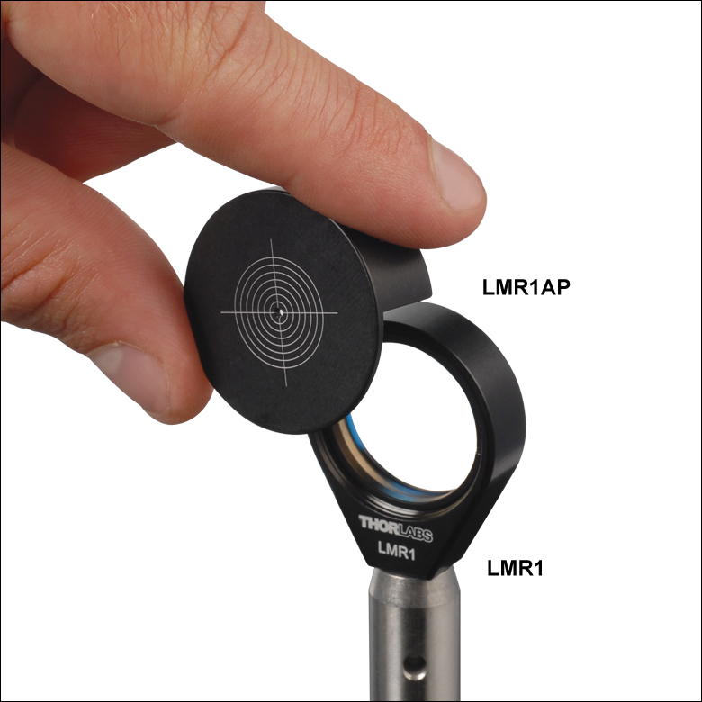
How to make sure that beam goes through a center of a lens?
We can use a target or we can make sure that the centers of beam without a lens and with a lens overlap. The second can be done by adjusting lens’s horizontal and vertical positions, while looking in the far-field.
A target for a lens, Taken from here
Which side of a lens should face a focal point?
To reduce spherical aberrations we would place the curved side towards plane incoming light and plane side towards focus point, an explanation could be found here. Lenses which we typically purchase in Thorlabs are plano-convex spherical and because of their imperfections they would deform the beam quality due to aberrations. More about abberation and beam profile could be read here and here.
Lens doesn’t have a label, how to check it
If nobody marked a lens you can roughly estimate focal point by placing it near a table and try to see where it focuses light from the lamps above you.
Lens characteristics?
What is an NA?
NA, or numerical aperture, is a dimensionless quantity that characterizes the light-gathering and focusing capability of a lens or of an optical system. It is defined as NA = n * sin(θ), where n is the refractive index of the medium and θ is the half-angle of the maximum cone of light that can be focused by the system. A higher NA corresponds to better resolution and light-gathering capability.
As a rule of thumb if wavelength of your laser is 1 um, your beam has 1 mm waist going through a 100 mm lens, it will result in 100 um waist.
Which waist do I expect after a lens?
The diffraction-limited spot size at the 99% contour is given by: , where λ = wavelength, ƒ=focal length and w = input beam radius at the 1/e^2 point, more here.
Typically used lenses and their applications
Lenses which we typically purchase are either plano-convex and plano-concave spherical lenses or aspheric lenses. Applications for the first type of lenses are listed below. Aspheric lenses should not introduce spherical abberations, thus they can be used with light coming out of a fiber or a diode. Cylindrical lenses can be used to correct elliptisity of the beam, for example emitted by a diode or after a tapered amplifier.
Applications
Telescope is used to change the size of the beam
Changing size of a beam waist with a two-lens telescope.
Focusing beam to pass through an aperture, onto a photodetector
Beam cleaning, you can use a pinhole to produce a circular beam, see more in beam profile SECTION.
Fibers and diodes emit fast expanding beam to collimate it you need a lens with high NA, typically with small focal length so you can place it close to the source before a beam expands too much.
Fourier image of a beam
Talbot imaging
Changing elliptisity: it is done in the same manner as we were changing the size of the beam in the first application. Construct a telescope of two cylindrical lenses to change aspect ratio of your ellipse.
AOM: answers
How are they used?
Acousto-optic modulators (AOMs) are typically used to control the intensity, frequency, and direction of laser beams separately or together. Applications include (1) switching laser on/off, creating pulses of tens of ns or longer; (2) frequency shifting; (3) controlling phase between two paths, for example for interferometric purposes; (4) controlling beam position; (5) time-dependent modulation of intensity, frequency, and/or phase.
What is a principle of operation?
The principle of operation of an Acousto-optic modulator (AOM) relies on the acousto-optic effect, which involves the interaction between sound waves and light within a transparent medium. When a radiofrequency (RF) signal is applied to a piezoelectric transducer bonded to the AOM’s crystal, it generates a traveling acoustic wave in the crystal. This acoustic wave induces a periodic change in the refractive index of the medium, effectively creating a moving diffraction grating. As light passes through the medium, it is diffracted by the grating, resulting in the modulation of the incident laser beam’s intensity, frequency, and direction.
Image taken form AA opto-electronic. Shows what is inside of AOM with a beam being diffracted by an acoustic wave.
Where will be the +1 order with respect to RF connector?
Further away from the RF connector. By momentum conservation law to have higher frequency would mean to get a kick along acoustic wave travelling direction.
Here is a diagram of the first order appearing further away from the RF knob.
What is a propagation delay in AOM?
Delay between the RF signal being transmitted by a piezo-element to a crystal and time while the acoustic-wave travels to a beam. In the same manner the rise time of AOM would be limited by beam size the velocity of acoustic wave.
The beam has non-zero waist, so an acoustic wave takes time to propagate across, which results in non-zero rise time.
How to set up the AOM in an experiment?
Which equipment is required?
You would need an RF source, an RF amplifier, and AOM itself.
What are typical operational parameters?
Typical values: Central frequency of RF 50–200 MHz, bandwidth ~20 MHz, required RF powers are 1–2 W, 80% efficiency, 20 ns rise time.
How to align AOM?
Typically you put an AOM on a mount which has both horizontal and vertical adjustment. Make sure that beam fully passes through AOMs aperture. Place a paper 20-30 cm away and rotate AOM in horizontal plane to see a faint +1 or -1 order. Place an iris to block 0th order. Optimize with one coupling mirror and AOM holder to get specified efficiency.
A signal generator is connected to an amplifier, which is connected to an AOM through an SMA cable. An optical beam is refracted inside an AOM and the zeroth order is blocked by an iris.
To focus or not to focus?
Typically apertures can handle the beam diameter. If you want fast response times you need to focus. Although you don’t want to go too tightly as efficiency of diffraction starts dropping, I think beam doesn’t see enough nodes and antinodes of an acoustic wave.
Difference between BD and AOM?
BD stands for beam deflector. A BD is designed to have continuous scanning of angles, for this they are designed to have large crystals (30 mm or more), which allow to have large beam diameters, decrease optical divergence and increase resolution. Summarizing BD better handle continuous scanning of frequencies/angles and AOMs are supposed to handle switching on/off better.
Polarization optics: answers
Which polarization can laser beam have?
Typically laser outputs linear polarization, which is prepared inside of it with polarization selective resonator.
Specify meaning of linear, circular and elliptical polarizations with equations.
In linear polarization, the electric field oscillates along a single axis, while in circular polarization, the electric field rotates in a circular pattern as the wave propagates. Elliptical polarization is a general case that encompasses both linear and circular polarization, where the electric field traces an ellipse in its plane of propagation. Additionally, the polarization can be either left-handed or right-handed, depending on the rotation direction.
An electric field could be written in HV basis
Different linear polarization would have different ‘weights’ for H and V components, for H and vice versa. The diagonal linear polarization has the same amplitudes of HV components , if , this would be +45 polarization:
In case of difference between phases, this will be -45 polarization:
If phase difference between components is , this would be one of circular polarizations:
What is PBS and BS?
PBS stands for polarizing beam splitter, an optical element that separates an incoming beam into two orthogonal polarization components. Typically, it transmits one linear polarization (horizontal) and reflects the orthogonal state (vertical), directing them along separate paths. BS stands for beam splitter, it divides an incoming beam into two parts disregarding polarization. The splitting ratio can be chosen to be 50:50 or other desired values, although it is not adjustable once a BS is produced.
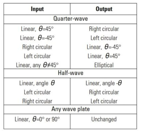
What is HWP and QWP? How to work with them?
HWP and QWP stand for half-wave plate and quarter-wave plate, respectively. These are birefringent optical elements used to manipulate the polarization state of a light beam. A HWP introduces a phase shift of π between the ordinary and extraordinary rays, effectively rotating the polarization axis of linearly polarized light. A QWP introduces a phase shift of π/2, which can be used to convert linear polarization to circular polarization and vice versa.
Below is a table of transformations taken from here
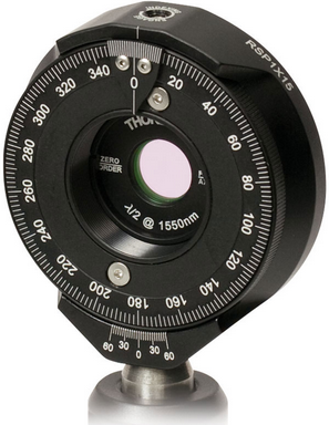
You would typically mount it in a rotating holder, which allows to get a required polarization via rotation of the HWP or/and QWP.
Multiorder vs single order HWP and QWP?
Multiorder and single-order wave plates refer to the design of a waveplate, which affect their performance and the range of wavelengths they can work with. Multiorder wave plates achieve the desired phase shift by stacking together odd number of waveplates, making them sensitive to wavelength changes. Single-order wave plates, on the other hand, use a single internal reflection and refraction to achieve the desired phase shift, making them less sensitive to wavelength changes but generally thicker. Single-order wave plates are preferred for broadband applications. I noticed that our multiorder waveplates designed for 780 nm, don’t work at 795 nm.
Polarizer and principle of work
A polarizer transmits light with a specific polarization state; the working principle of a polarizer can be based on different phenomena, such as absorption, reflection, or birefringence. A common example is the linear polarizer, which is typically made of anisotropic materials like Polaroid film. When unpolarized light passes through a linear polarizer, only the electric field oscillations parallel to the polarizer’s transmission axis are transmitted, resulting in a linearly polarized output beam.
Exercise:
Let’s assume that light is passing through a few polarizers. Let’s start our thought experiment by positioning a linear polarizer to pass |H> component, after which we place one more linear polarizer oriented vertically |V>. These two polarizers being orthogonal to each other would fully block the light. Let’s continue our thought experiment by placing a linear polarizer oriented at 45 in between these two, will we still not see any light after these three polarizers?
Three polarizers placed into a single path.
Answer
Strikingly this would make some portion of the light to reach an observer. A well described explanation is presented here. I can explain it from two points of view. First, a formal explanation, could be written in a quantum mechanical framework. Each polarizer will act as a projector in a relevant basis. As a reminder the first polarizer have an associated projector .
We can assume that the light is initially polarized along the axis of the first polarizer. So the 1st polarizer doesn’t modify our state. To see what the second polarizer does we switch into a diagonal basis, where state is a superposition . The second element (polarizer at 45 degrees) transmits only portion of the light, getting us a state . To see effect of the third element, we can switch back into basis: and the third polarizer making one more projection leaves us with state, which would result in non-zero light being transmitted.
Although this quantum mechanical description which gives a correct (or experimentally observed answer) would mislead us in thinking that this is a quantum effect. Although we can describe it on a classical level.
On the classical level we should not think of a polarizer as of a filter: it doesn’t simply absorbs light not aligned along its axes. In fact a polarizer rotates polarization axes, or in other words absorbs and reemits light along the axes its dipoles are are aligned.
Fiber optics: answers
What is the basic principle?
A fiber guides light along its length by exploiting the phenomenon of total internal reflection (TIR). An optical fiber typically consists of a core with a higher refractive index surrounded by a cladding with a lower refractive index. When light enters the fiber at an angle within the acceptance cone, it undergoes multiple TIRs at the core-cladding interface, effectively being confined within the core and propagating along the fiber with minimal loss.
What is a single-mode and multimode fiber? Which one to choose?
Single-mode fiber has a smaller core diameter (typically around 1 micrometer) compared to multimode fiber, allowing only the fundamental mode to propagate. Single-mode fibers exhibit lower signal attenuation and dispersion, making them suitable for long-distance and high-bandwidth applications.
Multimode fiber is designed to carry multiple modes of light simultaneously. It has a larger core diameter (commonly 50 or 62.5 micrometers), allowing multiple light paths or modes to propagate.
Have never seen people using Multimode fiber, except when it is an intention of experiment to preserve higher spatial modes of light.
What is a polarization maintaining fiber?
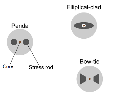
A polarization-maintaining (PM) fiber is a type of optical fiber designed to preserve the polarization state of the input light along its length, even in the presence of external perturbations. PM fibers have a built-in birefringence, typically achieved by introducing geometric or stress-induced asymmetry in the core or the cladding. This birefringence results in two orthogonal polarization modes, referred to as slow and fast axes, that maintain their relative phase difference along the fiber, thus preserving the input polarization state. There are three typical types of crosssections: panda, elliptical, and a bow-tie (see an image, source is here)
How to align a fiber?
The typical setup will consists of a fiber mount, two mirrors and a short focal-length lens.
Which lens to use?
A lens can be used to focus the input light beam onto the fiber’s core to maximize coupling efficiency. Commonly used lenses include aspheric lenses, gradient-index (GRIN) lenses, and objective lenses. We typically use aspherical lenses with focal lengths of 8, 11, and 15 mm. The lens should be placed closely to a fiber and to be adjustable within a mm.
How to couple light into a fiber?
The core diameter is small so it is one of the most tedious alignments in the lab. The bare minimum will be to have two mirrors in front of a fiber coupling stage. The fiber coupling stage needs an adjustable mount for a lens along the beam.
The alignment setup for a fiber.
The easiest technique is to use back-coupled light from another source. If you have a fiber visual fault locator or already prealigned fiber, couple it backwards through your fiber and use it as a reference to align the incident beam. After that connect the end of you fiber to a powermeter, typically you will see tens of nanowatts of coupled power. Using one mirror you can try to slightly increase it. After that use walking technique to align to mirrors in order to maximize the power.
Why coupling is still low? Is a fiber damaged?
You can use a fiber microscope to check the surface of a fiber. Typically it requires just wet cleaning to remove dust from the surface.
Some of the damage cannot be removed by cleaning, it could mean that fiber end was burnt. In this situation you can try to polish fiber end.
How to work with polarization maintaining fibers?
When working with polarization-maintaining fibers, it is essential to align the input polarization state with the fiber’s principal axes (slow or fast axes). Use a polarizer, half-wave plate, or a combination of a quarter-wave plate and a half-wave plate to set the input polarization state. Actively monitor the output polarization using a polarization analyzer or a fiber-based polarimeter (see picture).
We can check polarization after a fiber by sending a beam on a PBS and measuring two output arms with two orthogonal polarizations. Two detectors are necessary if you suspect that overall power of the beam can drift.
What can induce polarization rotation? There are a few factors, which you should keep in mind to improve performance:
Use appropriate mating sleeves or adapters designed for PM fibers to minimize losses and maintain polarization extinction ratio.
Avoid excessive bending or twisting of the PM fiber, as it may introduce strain-induced birefringence that can affect the polarization performance
Keep temperature of a fiber stable, if fiber travels across a room use an insulating sleeve to isolate from the room temperature fluctuations.
Use shorter fibers if it is possible.
How to make sure that polarization is aligned along axis of the fiber?
To ensure that the polarization is aligned along the fiber’s axis, particularly for PM fibers, align the input beam’s polarization state with the slow or fast axis of the fiber. For this you need to setup polarimeter measurement as on the previous picture and send signal of two detectors to an oscilloscope. By quickly shaking a fiber see how power goes from one detector to another, align a fiber just before the fiber to minimize those oscillations. Alternatively, to induce polarization rotation you can place a speaker with some music on a fiber.
FC/PC or FC/APC types
FC/PC and FC/APC are types of fiber optic connectors designed for different purposes. FC/PC (Ferrule Connector/Physical Contact) connectors have a flat or slightly curved end face, which allows for physical contact between the two mating ferrules, minimizing insertion loss. FC/APC (Ferrule Connector/Angled Physical Contact) connectors have an angled end face (typically 8 degrees) that helps reduce back reflections and return loss, which is crucial for high-power and sensitive applications.
Pros and cons of optical fibers?
(+) can send light, where direct path is tricky: across rooms, different tables
(+) cleans spatial profile of your laser
(+) allows to use many fiber coupled components: detectors, modulators, amplifiers, and so on
(+) compact and easy to change setup
(-) is lossy
(-) varies polarization
(-) coupling efficiency could be low
(-) it is a nonlinear crystlal, which would cause nonlinear effects to appear
Fiber beam-splitters to use or not to use?
We use fiber beam-splitters, which could have different number of input/output ports. It is very convenient to use them for laser cooling, since you need to split a single beam light into four or six beams. There are a few available options in Thorlabs, as well we ordered some custom designed BS Evanescent optics.
Optics cleaning: answers
Typical contaminants?
The quality of the surface plays an important role. A contaminant on a surface could cause scattering, absorption, and damage of a surface. Two main contaminants are dust and fingerprints.
Fingerprints damage optics, clean it quickly! Fingerprints on optics can introduce contaminants, such as oils and debris, which can degrade optical performance and potentially damage the surface of the optic. If you notice fingerprints on an optical component, it is essential to clean the surface promptly.
What do I need to clean optics?
compressed air, keep it upright, it could condense on your optical surface
solvents: IPA, methanol, ethanol, and acetone. Low residual factor and high purity.
lens tissues
container with a dropper. Should be compatible with your solvent, in many cases I have seen acetone to dissolve, rubber dropper.
gloves, lint-free and powder-free.
forceps. metal and lockable
Cleaning technique
To properly clean optics, follow these steps:
Handle the optics with clean gloves to prevent further contamination.
Use a gentle, dry cleaning method first. This may involve using a clean, compressed air source or a canned air duster to blow off loose particles and dust from the optic’s surface.
If the dry cleaning method does not suffice, proceed with a wet cleaning method. Moisten a lint-free, non-abrasive cleaning wipe or swab with a high-purity solvent.
Gently wipe the optic’s surface with the moistened wipe or swab, applying minimal pressure. Use a sweeping or dragging motion, starting from the center and moving outward toward the edges. Avoid circular wiping motions, which may redistribute contaminants.
Inspect the optic using a bright light source and looking on its reflection.
Mirrors: answers
What is an S and P polarization?
S and P polarization refer to the two orthogonal components of linearly polarized light with respect to a plane of incidence. S polarization (from “senkrecht,” German for perpendicular) corresponds to the electric field component perpendicular to the plane of incidence. P polarization (from “parallel”) corresponds to the electric field component parallel to the plane of incidence. These terms are commonly used when analyzing the reflection and transmission properties of optical elements, such as mirrors and beam splitters.
Which parameters characterize surface quality?
Surface quality is characterized by parameters that describe surface imperfections, such as scratches, digs, and roughness. The scratch-dig specification is a common measure of surface quality, represented as a pair of numbers (e.g., 40-20 or 10-5). The first number refers to the visibility of scratches, while the second number represents the size and density of digs. Lower numbers indicate higher surface quality. Surface roughness, typically measured in angstroms or nanometers RMS (root mean square), characterizes the microscopic deviations from a perfectly smooth surface, which can impact the performance of high-precision optical systems.
How much power any element can handle?
The amount of power an optical element can handle depends on factors such as the material, the coating, and the size of the component. Optical elements have damage thresholds, typically specified in terms of energy density (e.g., J/cm² for pulsed lasers) or power density (e.g., W/cm² for continuous-wave lasers). Exceeding these thresholds can cause thermal stress, ablation, or other damage to the element. When selecting an optic, ensure that its damage threshold is suitable for the intended application.
How to choose a necessary mirror? Metallic vs dielectric mirrors?
When choosing a mirror, consider factors such as reflectivity, damage threshold, wavelength range, and environmental stability. Metallic mirrors, made from materials like aluminum, silver, or gold, offer broadband reflectivity and are generally less sensitive to the angle of incidence. However, their reflectivity is often lower than dielectric mirrors. Dielectric mirrors, made by depositing alternating layers of high and low refractive index materials, can achieve very high reflectivity (>99%) but are typically designed for specific wavelength ranges and angles of incidence.
What is an AR coating?
An anti-reflection coating, is a thin-film coating applied to an optical surface to reduce reflections and increase light transmission. AR coatings are designed for specific wavelength ranges and typically consist of multiple layers of dielectric materials with varying refractive indices.
How to align two mirrors?
How to align a beam along a desired line
Two mirrors allow to align a beam along any line, make it go through two points. Choose two reference points: one in a near-field and one in a far-field, the further they are separted the more precise your alignment will be. You can place irises to mark those. Use the closest mirror to the source to align the near-field and the second mirror to align beam in the far-field.
Two mirrors have enough degrees of freedom to align beam in any direction.
What is a walking technique?
If you don’t have a clear access to monitor, for example if you align a fiber or a resonator. Than you will try to have a power meter or a photodetector reading to inform you if you are improving alignment. Having this monitor set you would try to misalign 1 knob of one mirror in some direction (remember the direction!). Now you can compensate with the 2d mirror and hopefully to get even better. If reading didn’t improve try other direction (clockwise/counter-clockwise) and try other knob. Sometimes you need to make a few rounds of optimization of each pair of knobs.
How to align two mirrors with a lens?
There are situations when you don’t have a free path to align two beams, if you are working with a prebuilt system. One of special cases would be to align mirrors with lenses in the beam.
Which optical mount to use?
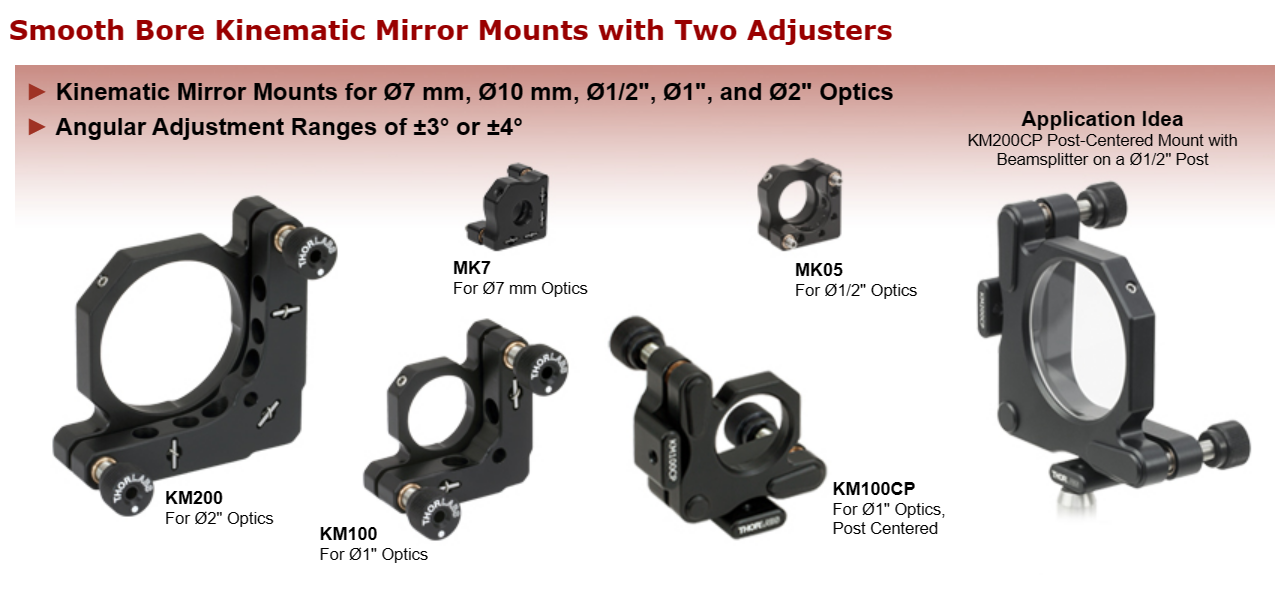
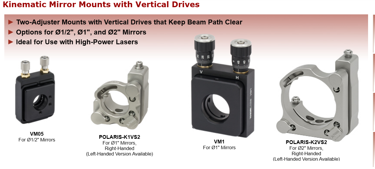
Typically we use mirrors with two knobs. Like Thorlabs KM100. One corresponds to horizontal, other to vertical movement. Sometimes you want bigger range of angles, thus a third middle knob will help you. If you need more precision there are more precise knobs. For example VM1 and Polaris mounts, but other companies cell mirror mounts as well.
When to use a curved mirror?
If you are building a resonator you want to match Gaussian beam propagation, thus requiring a curved surface. Layertec and thorlabs?
Faraday isolators: answers
Principle of work?
The principle of operation of a Faraday isolator is based on the Faraday effect, a phenomenon in which the polarization plane of light rotates when it passes through a material in the presence of a magnetic field. In a Faraday isolator, a Faraday rotator made of a material with high Verdet constant is placed between two polarizers. The magnetic field is applied along the direction of light propagation. When light enters the Faraday rotator, its polarization rotates, allowing it to pass through the first polarizer. However, light traveling in the reverse direction experiences a second rotation upon exiting the Faraday rotator, leading to a misalignment with the second polarizer and preventing its transmission. This unidirectional transmission makes Faraday isolators effective in preventing optical feedback in laser systems.
Constitute components
The input beam passes through a first polarizer fully, magnetic field rotates polarization preparing polarization at 45 degrees, which passes through the second polarizer. The back-reflected beam after passing through the second
Why and when do we use them?
Faraday isolators are used in laser systems to prevent backreflection of light into the laser resonator. It is important as a small amounts of light can lead to fluctuations in output power and linewidth broadening.
How would you adjust it?
Aligning a Faraday isolator involves optimizing the orientation of the optical polarizers to receive highest transmission of forward beam and highest suppression of the backreflected beam.
Before you start remember that it contains a constant magnet, try not to use a magnetic elements around it, or use it cautiously! Mount your Faraday isolator, ensuring that it is mechanically stable.
Adjust the Input and Output Polarizers. Start by adjusting the input polarizer to minimize reflection of this beam. Adjust the second polarizer to maximize transmission once again. You can make a few adjustment round of these two elements. This will automatically make sure that the reflected beam is blocked.
Beam profile: answers
What is a Gaussian beam?
A Gaussian beam is a fundamental solution of the paraxial wave equation, characterized by a bell-shaped intensity profile and a specific transverse spatial mode structure. It represents a common type of laser beam with a well-defined waist and divergence.
What is a Bessel beam?
A Bessel beam is a type of non-diffracting beam characterized by its ability to propagate without spreading over a certain distance. It features concentric rings of light, and its unique property of self-reconstruction allows it to maintain its shape even when obstacles are introduced along its path.
What is M^2 factor?
The M^2 factor, or beam quality factor, is a measure of how closely a laser beam’s spatial mode resembles that of an ideal Gaussian beam. A perfect Gaussian beam has an M^2 value of 1, while higher values indicate deviations from the ideal beam shape.
Mode cleaning techniques?
as well described on Thorlabs website
Mode cleaning techniques, as described on Thorlabs website, likely involve methods to selectively filter and enhance specific transverse modes in laser beams. This can include the use of spatial filters, interferometers, or other optical elements to improve the beam quality and suppress unwanted modes, contributing to a cleaner and more well-defined output.
How would you use an anamorphic prism pair?
An anamorphic prism pair is used to transform the elliptical shape of a laser beam into a circular one or vice versa. By exploiting the dispersive properties of prisms, this optical system adjusts the beam’s aspect ratio, providing control over the divergence characteristics along the orthogonal axes of the beam. This is valuable in applications where matching the beam shape to the characteristics of subsequent optical components is crucial for optimal system performance.
Diffraction grating: answers
Angle rules
Diffraction is governed by the Huygens-Fresnel principle, stating that each point on a wavefront can be considered as a secondary source of spherical wavelets. The interference of these wavelets results in the observed diffraction pattern. The diffraction angle and pattern characteristics depend on the wavelength of light and the size and shape of the diffracting aperture or grating.
Application with diode lasers
Diffraction gratings are often used in diode lasers to select specific wavelengths or to provide feedback for wavelength stabilization. In a littrow configuration a 1st order of diffracted beam is relfected back into a diode laser forming an external resonator, while the zeroth order goes out of the resonator.
Application for UFO
In ultra-fast optics, diffraction gratings play a crucial role in dispersing and manipulating ultrashort laser pulses. Gratings can be employed in pulse compressors and stretchers to manage the spectral and temporal characteristics of femtosecond or picosecond laser pulses. By adjusting the groove density and angle of the grating, dispersion can be controlled, enabling the manipulation of pulse duration and spectral content in ultra-fast laser systems for applications in fields like ultrafast spectroscopy and laser material processing.
Other neat examples of diffraciton gratings usage:


 A target for a lens, Taken from here
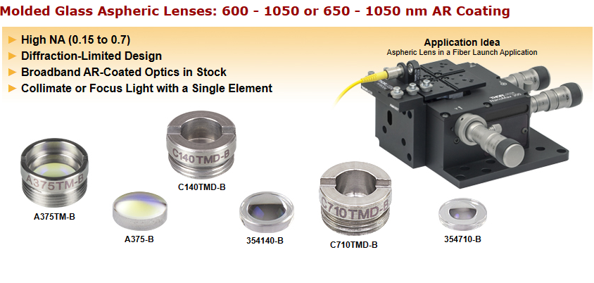


BD stands for beam deflector. A BD is designed to have continuous scanning of angles, for this they are designed to have large crystals (30 mm or more), which allow to have large beam diameters, decrease optical divergence and increase resolution. Summarizing BD better handle continuous scanning of frequencies/angles and AOMs are supposed to handle switching on/off better.
 You would typically mount it in a rotating holder, which allows to get a required polarization via rotation of the HWP or/and QWP.